Load Test On Seperately Excited DC Motor
Separately excited dc motors are very often used as actuators in industrial applications. These actuators have low friction, small size, high speed, low construction cost, operate safely without the use of limit switches and generate moderate torque at a high torque to weight ratio. DC motors are preferred over ac motors because of their lower manufacturing costs and, ease of controller implementations, since their mathematical model is simpler.
Construction of D.C. Machine:
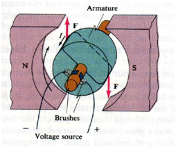
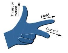
The main parts of a DC machine are Field winding, Armature winding, Yoke, Commutator segments and Brushes. When acting as motor both the armature and field windings are given DC supply or the field may be created by permanent magnets. Working Principle of D.C. Motor: When a current carrying conductor is placed in magnetic field, it experiences a mechanical force whose direction is given by Flemings left hand rule.
Current flows through both field and armature windings. Main flux in the machine is produced by the field winding. Current flowing through the armature winding interacts with the main flux to produce the rotational force (Torque). Commutator and brush arrangement is used to change the direction of armature current as the armature conductors pass under different polarities of magnetic field. This leads to production of continuous and unidirectional torque. As the armature starts rotating, it cuts the flux lines produced by the field. This action is similar to the generator action and hence EMF is induced in the armature winding. The direction of this induced EMF by Fleming's right hand rule and is in direct opposition to the applied voltage (observe: the direction of current which is same as direction of voltage).