
Open Circuit Test on Three Phase Alternator
Open Circuit Test on Three Phase Alternator
- Close the DPST (Double Pole Single Throw) switch connecting the armature winding of DC shunt motor to supply. Rheostat is used as a potential divider. It is used to increase or decrease the stator voltage of DC shunt motor.
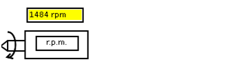
- Bring the DC shunt motor to rated speed (1500rpm) by clicking the arrows on rheostat.
- Now, even though field voltage of the generator is zero, we can observe some value at generator output due to residual magnetism.
- Alternator is brought to synchronous speed (1500rpm) by using DC shunt motor.
- As DC shunt motor is connected mechanically to alternator, So both machines rotate with same speed. Therefore we can observe speed of alternator.
- Close the DPST switch connecting the alternator to supply through rheostat.
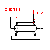
- Now increase the field current of alternator by using the rheostat connected to field winding of the alternator.
- Observe the values of ammeter and voltmeter.
- Store this data by clicking "Start Storing Data"
- Go on repeating this procedure till sufficient readings are stored.
- Now display the data by clicking "Show data". For Ex it will display data as shown:
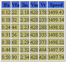
- Vfa=field voltage of alternator
- Ifa=field current of alternator
- Vin=input voltage DC motor
- Iin=input current of DC motor
- Vt=terminal voltage
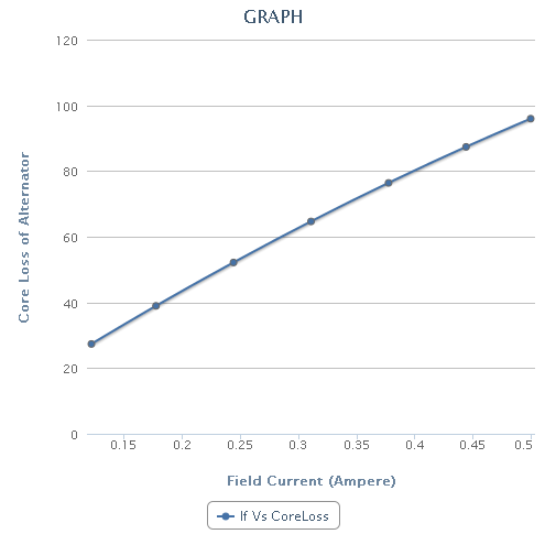
- Now select one of the graph from available graphs and use "Generate graph" to plot the graph. For Ex.
- Slowly decrease the excitation of DC shunt motor to zero.
- Switch off supply.