
Short Circuit Test on Three Phase Alternator
Short Circuit Test on Three Phase Alternator
- Stator terminals are Short Circuited in order to perform SC test on alternator.
- Close the DPST (Double Pole Single Throw) switch connecting the armature winding of DC shunt motor to supply.
- Rheostat is used as a potential divider. It is used to increase or decrease the stator voltage of DC shunt motor.

- Bring DC shunt motor to its rated speed (1500rpm) and Alternator is made to run at its synchronous speed (1500rpm) using DC shunt motor.
- As DC shunt motor is connected mechanically to alternator, So both machines rotate with same speed. Therefore we can observe speed of alternator in digital tachometer.
- Close the DPST switch connecting the alternator to supply.
- Vary DC excitation of alternator in steps to increase field voltage to its rated value.
- Observe the readings of voltmeter and ammeter. 9 Store this data by clicking "Start Storing Data"
- Go on repeating this procedure till sufficient readings are stored.
- Now display the data by clicking "Show data". For Ex it will display data as shown.
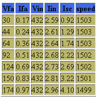
- Vfa=field voltage of alternator
- Ifa=field current of alternator
- Vin=input voltage DC motor
- Iin=input current of DC motor
- Isc=short circuit current
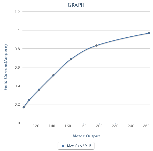
- Now select one of the graph from available graphs and use "Generate graph" to plot the graph. For Ex.
- Slowly reduce the excitation and field rheostat of shunt motor to zero.
- Switch off supply.